blog til projects meta feed
~ / blog / Writing an OLED display driver in MicroZig 2024-02-28 | 7 minutes
Update 2025-03-06 / There is now an SSD1306 driver available in the official MicroZig repository.
# Beginnings
Recently, I have been messing around with a Rapsberry Pi Pico. Initially, I started out with MicroPython, as this is what most of the documentation for working with the Pico uses. However, this was honestly a little boring, as I seem to end up doing every project in Python. I wanted something a little more engaging for my brain, a little spicier. It’s Friday afternoon!
This is where Zig comes in. I have been seeing a lot of buzz around Zig as a language. It aims to be a drop-in replacement/improvement for C, and the interoperability that it provides with C libraries really intrigued me.
However, I wanted my hobbyist hijinx to be the sort of “dabble in a new language, try out some different things” sort of fun, rather than the looming “figure out how to create Zig executables that can run on and drive embedded systems” sort of hell. Luckily for me, some wonderful folks have done the heavy lifting in this department: MicroZig.
This project is great. It is still in the early-ish stages, with full support only available for (you guessed it) the RP2040. But things are moving fast, and the project is actively developed.
This is exactly what I needed, so I jumped right in. Following along with the Raspberry Pi examples, I quickly had some working code for flashing some LEDs. Cool!
At this point, I remembered about a small OLED screen that I had, perfect for exactly this kind of tinkering. Time to get to work on on driving this bad boy. As is always the first step with hardware, I went off on a datasheet hunt. It took me an embarassingly long time to find, but I eventually figured out that I was the proud owner of an SSD1306 OLED screen. (This is the datasheet for the 128x64 version, but I have the 128x32).
Now, as datasheets go, this is pretty good. We have all of the available commands, and instructions for how to write to the display RAM (for showing stuff on the screen). But how do we send these commands? This is also in the datasheet: I2C. There is a brief explanation in there about what the device is expecting, but I needed to do some more digging, as this is my first time dabbling directly in I2C communication.
After hunting around a bit, I had another look in the MicroZig examples, and found something very useful: there is an I2C driver included as part of the RP2040 HAL. The example that they provided scans for available I2C devices, and prints their addresses over UART. This would be ideal as a starting point, if I could just read the UART. Normally, when connected to my laptop, I could just print these values via serial over USB. However, this is an exisiting issue in the MicroZig repo, and is currently not supported. At this point, I ordered a UART to USB adapter, and resigned to leave the project alone until it arrived.
…
…
…
But where is the fun in that?! Something about this project wouldn’t let me just put it down for a couple of days, so while I waited for my delivery I started trying to communicate with the screen regardless. How hard could it be?
# Hard stuff
I started out by trying to just send commands to the screen. I knew the default address of the device from the datasheet (0x3C), and started firing commands over I2C to try and provoke any sort of reaction. The MicroZig driver allowed me to this super easily. Just setup the I2C device, and then send data using the write_blocking function. I put the sending code inside a little function to make things easier to parse:
const i2c0 = i2c.num(0);
_ = i2c0.apply(.{
    .clock_config = rp2040.clock_config,
    .scl_pin = gpio.num(21),
    .sda_pin = gpio.num(20),
    .baud_rate = 400000,
});
pub fn send(bytes: []const u8) !void {
    const a: i2c.Address = @enumFromInt(0x3C);
    _ = i2c0.write_blocking(a, bytes) catch {
        led.put(1);
    };
}
The SSD1306, stood firm, resolutely denying me even a single pixel. There is no feedback for any of this, except a single flashing LED to let me know my code is running. I am shooting from the hip (and missing).
It was at this point that I became really impressed with Zig’s compilation, and in particular the caching. As part of this process, I was messing around a lot with my code, and then building and loading onto the Pico with the following command:
zig build; picotool load -x zig-out/firmware/pico_i2c.uf2
I became convinced that something was going wrong at this step; partly because I only had minimal feedback for my loaded changes, but also because the compilation was so damn fast. I would make significant changes to the code, and it would rebuild and load onto the board almost instantly. Even though I was seeing the changes I made reflected on the board through the LED, I still occasionally deleted the zig-out and zig-cache folders just to be absolutely sure that things were rebuilding properly. But no, it really is just that fast.
Back to the display: in order to send a command, you must find send a command control byte (0x00). This prepares the screen to act on the next byte that it receives. For example: sending 0x00, followed by 0xA5, should turn the entire display on:

This was definitely not happening, and I was definitely missing something.
So, I began searching around for other driver implementations. Luckily, this is a very popular OLED display for these kind of projects, so there was plenty of options. The first one I found was the source code for the Adafruit MicroPython driver. This provided me with some reassurance that I was on the right path with the commands that I was sending, and also provided me with some useful info about the differences between the 128x64 and the 128x32, as I still wasn’t able to find the specific datasheet for my model. Most importantly however, it provided we with some initailisation commands. Each of the subclasses contained a method _initialize, which performed a long list of commands to, funnily enough, initialise the display.
This was a big breakthrough! All I have to do is send the initialisation commands, and my screen will be working perfectly! Well, it wasn’t to be. I dutifully entered all of these commands and… nothing happened. My screen stared me down yet again, blank as ever.
Not to let this drag me down, I kept searching, this time focusing in on the initialisation commands. I found this repo, written in C. I briefly messed around with linking this C code to my Zig project, but got bogged down with getting it to play nice with MicroZig. However, the repo did provide me with some fantastic information: a full flowchart for the initialisation commands, and the source for it. Which was (you guessed it again), the datasheet that I already had. If RTFM applies to software, it applies 1000 times over to hardware1.
Surely I was almost there? Well, almost yes, but not quite. Matiasus’s commands didn’t seem to work for me either. Looking back, this was probably a small typo or something on my end, but it is difficult to notice when you are staring at a bunch of hex.
The thing that made the breakthrough for me was this holy grail of a blog post. Just exactly what I needed at exactly the right time. It calmly and thoroughly explains the process of communicating with the display, as well as the initialisation. I was mostly right in what I interpreted from the datasheet, but it is always nice to have things confirmed by someone who clearly understands this better than you. This led me to the following initialisation commands:
const INIT = [_]u8{
    CONTROL_COMMAND, 0xAE,
    CONTROL_COMMAND, 0xA8, 0x1F,
    CONTROL_COMMAND, 0xD3, 0x00,
    CONTROL_COMMAND, 0x40,
    CONTROL_COMMAND, 0xA0,
    CONTROL_COMMAND, 0xC0,
    CONTROL_COMMAND, 0xDA, 0x02,
    CONTROL_COMMAND, 0x81, 0x7F,
    CONTROL_COMMAND, 0xA4,
    CONTROL_COMMAND, 0xD5, 0x80,
    CONTROL_COMMAND, 0x8D, 0x14,
    CONTROL_COMMAND, 0xAF
};
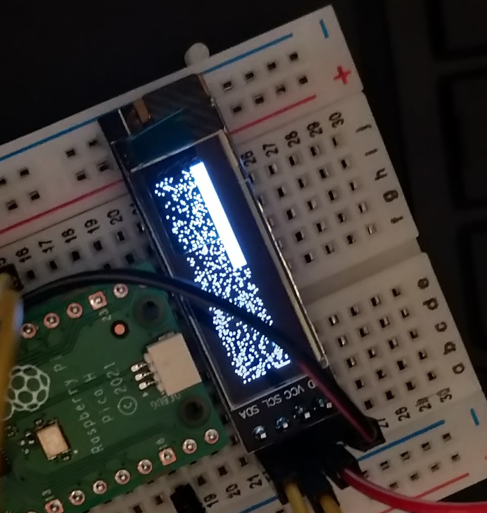
With Natesh’s blog post by my side, I finally, finally managed to get the display to do something:

Look at that. Glorious.2
Now treating Natesh with the kind of reverence they deserve, I followed their advice to try and turn the entire display on. This just involves writing ones to the entire display buffer. But, we first have to set up the device to expect this data.
Firstly, you choose the desired adressing mode for the display RAM, so that your pixels show up where you expect them to. The display is split into 4 horizontal “pages”, each 8 bits tall and 128 bits wide. You can address in one of three ways: page-wise, page-wise with automatic wrapping to the next page, and column-wise (also with automatic wrapping).
I settled for page-wise with automatic wrapping, as this is easiest to align in my head with physical writing3. Things are slightly complicated by the page structure, as you set all 8 height-wise bits of a given page with a single byte, but this doesn’t matter for just filling up the display.
The next thing is to set the range of pages and columns to draw to. This is useful for more complicated drawings and designs, but my range is just pages 0 -> 3 and columns 0 -> 127, as we are filling the entire display.
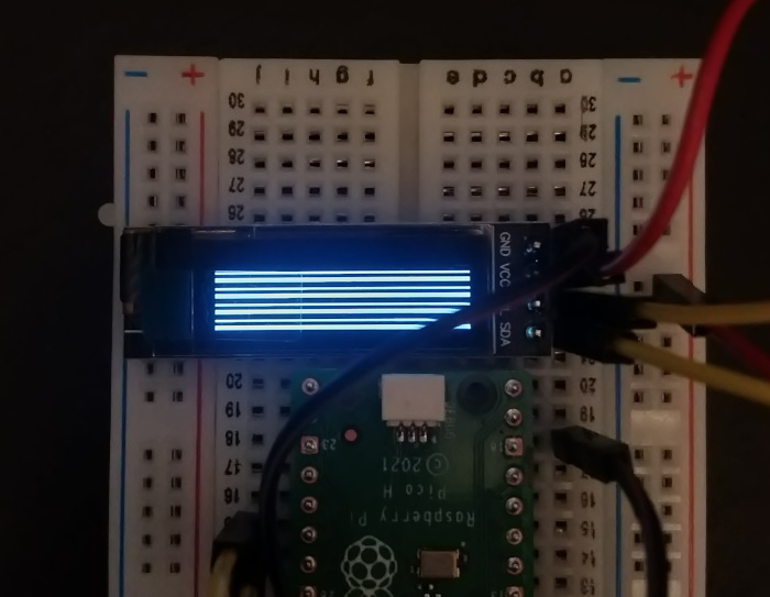
Once I got this all sorted out, I had my first attempt at filling the buffer. To nobody’s surprise, this didn’t work:

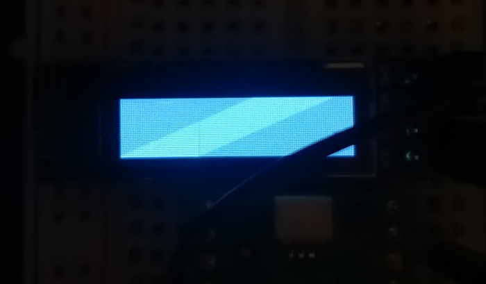
However, after a little bit of tweaking (and a hefty load of jank) I managed to get things working4:

Now this is progress! Finally, after about a day and a half of trying, the device is showing what I want it to.
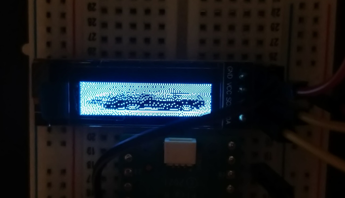
The next (and final) step of this process is to display an image on the screen. This feels like a big enough achievement that I can safely let my brain rest. I chose the following image as it will hopefully be clearly identifiable in only 4096 pixels5:

I used this tool to convert it into a byte array. I copied this into the code, covered my eyes, and hit enter…

Success! After quite a bit of tinkering, I can now display images on my little OLED screen. And, to top it all off, I got this working just before the UART-to-USB adapter dropped through my letterbox :).
# Conclusion
I really enjoyed this as a weekend project. Zig is a fun language to work with, and the MicroZig team have done a great job getting things working on embedded devices. It was immensely satisfying to break through and get things working, by slowly figuring things out. I was of course helped by some good repositories, and one fantastic blog post (thanks Natesh!). This is a good takeaway: if you are working on something, anything, write about it! Firstly because I want to read it, but also because it will undoubtedly help someone down the line.
The code for this project is available here if you want to use this as a starting point for your own adventures. I have not added anything since writing this blog post, but I will likely come back to it at some point (once I get through every other project!).
-
In my defence, it was on page 64 (sixty-four) of a 65 page manual ↩
-
I believe that all of these pixels were actually set by me, when I was firing commands at the device. Some accidental abstract art. ↩
-
Like, with a pen. ↩
-
To be honest, I am still not exactly sure what fixed things, or what was even going wrong in the first place. ↩
-
And because I like it. ↩
Articles from blogs I follow around the net
Switching from GPG to age
It’s been several years since I went through all the trouble of setting up my own GPG keys and securing them in YubiKeys following drduh’s guide. With that approach, you generate one key securely offline and store it on multiple YubiKeys, along with a back…
via Luke Hsiao's blog November 4, 2025Computer Says No: Error Reporting for LTL
Quickstrom is a property-based testing tool for web applications, using QuickLTL for specifying the intended behavior. QuickLTL is a linear temporal logic (LTL) over finite traces, especially suited for testing. As with many other logic systems, when a formu…
via Oskar Wickström November 1, 2025Cosytober 2025
Cosytober 2025 CosyTober is a “cosy alternative to #Inktober”. The idea is the same, all during October, each day a prompt is given and artists are asked to draw, paint or otherwise create something inspired by the prompt and post it to social media. I'…
via splitbrain.org - blog October 31, 2025Generated by openring


Last updated: 2025-11-08 16:06:19 +0000
v25.16.p1108
© Andrew Conlin 2023-2025
All rights reverse engineered